
Although the tool offers quite seamless edition and navigation through models and the tasks of particular actors could overlap, it is assumed that VIDE Programmer will take care of providing the model with behaviour by specifying method bodies. This assumes that the class model will be provided by Analyst / Designer as the starting point, though the Programmer may need to make corrections or refinements – for example, by specifying or altering operation signatures.
The general flow of development activities in this use case includes the following steps:
selecting and adjusting operation definitions that will provide the context to the behaviour
specifying (implementing) method bodies for those operations (using textual or visual VIDE PIM language)
storing those definitions in the model
executing the model, in order to test the behaviour specified, by invoking ad-hoc statements and queries over a model loaded into the Model Execution Engine
generating the code for the target platform selected.
Note that this flow may serve many various specific use cases, depending on the role of the code being specified, and depending on the purpose the model is run (for example, plain testing or validation involving the final user). In the following section the guidelines for this basic workflow are provided.
This task is aimed at development of UML/OCL behaviour model using VIDE, to become a method body or just to serve as an ad-hoc query or statement to be invoked against the Model Execution Engine. We’ll first focus on the latter as the more common and revisit the ad-hoc code in section 2.4.2.2.4.
This steps involves review and refinement of a class model as provided from CIM to PIM transformation and refined (or developed from scratch at PIM level) by Analyst / Designer. In case you create a new project using Topcased, set the project kind under eclipse by selecting “VIDE Project”. Then, create a class diagram by selecting New > UML Diagram in the Navigator window and ensure the Class Diagram is selected as the template.
Here, the usual way of developing class diagrams applies (in this description we assume using Topcased tool). The only VIDE-specific requirement is to use in the class diagram the primitive types coming from the OCL Standard Library, so that the resulting data items are capable of becoming parts of OCL expressions. See Figure 56.
Please, also make sure that the packages you are going to provide with VIDE-defined behaviour have the VIDE profile applied.

Figure 56: Selecting OCL Standard Library types in Topcased
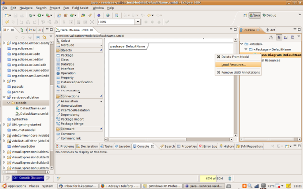
Figure 57: Connecting VIDE profile to the project
Moreover, you may want to include a special-purpose class and nominate it with stereotype «module», to serve as an entry point to your application (its attributes may set the contents of the application’s data storage, and its operations can offer the globally available functionality – which may include Web service operations to be published by the application). Figure 58 shows an example of such class.

Figure 58: Class serving as a module definition and a publisher of Web service operations
The VIDE-specific stereotypes are listed and briefly described in the list below:
«module» – a class with this stereotype serves as the place of definition for application’s entry point and its globally available behaviour and data. Objects of this class cannot be instantiated in a regular way. The name of such class has to be identical to the containing Package’s name. Running application can be considered a singleton instance of such class.
«PublishedService» marks a class whose selected operations should be available as Web service operation. Namespace and URL have to be provided as this stereotype’s attributes. A whole Web service definition can be produced from such a model without further input from the developer, using the default naming conventions.
«PublishedOperation» marks an operation inside a «PublishedService»-stereotyped class. This allows to selectively publish class’s operations.
«ConsumedService» marks a stub class for an external service to be consumed by VIDE-defined behaviour. You would not normally apply this stereotype by hand, but rather use a Web service description input feature of VIDE editor to produce a complete package of a consumed service. This stereotype cannot be combined with «PublishedService».
«Id» marks an attribute (String type is supported in this role currently) that uniquely identifies instance of a given class. In case the “Generate” stereotype attribute is set to true, you will not be required to set the value at object creation, as it will be auto generated by the implementation on the target platform.
«Persistent» marks a class whose instances are intended to be persisted on the target platform.
«Transient» is a stereotype of attribute inside class, which allow to exclude it from the persistent state of the instance of the method marked as «Persistent».
In order to make your model able to be run with the Model Execution Engine, please create one class with the «module» stereotype. As mentioned, its name has to match the name of its containing package.
For an introductory example – let’s try to create the following model consisting of 3 domain classes and one module class (see Figure 59: Introductory example – Simple Shop classes). This will be further refined in the following sections.
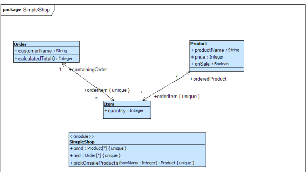
Figure 59: Introductory example – Simple Shop classes
When your model structure is precise enough to start specifying method bodies, you need to use the Repository Browser and Textual Editor components available in the VIDE perspective of your environment (the perspective should look as shown in Figure 60)
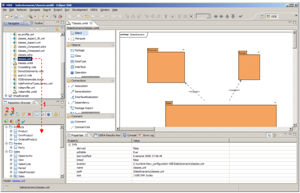
Figure 60: VIDE PIM perspective with a model loaded into Repository Browser
To open the model in the Repository Browser view (see Figure 60), you may just perform drag & drop of the .uml file from the Navigator window (1). Alternatively, you may use the “Load UML model” button (2) or activate the “Auto load Topcased class diagram models” switch (3) and open the class diagram in Topcased.
Note. Having the class diagram open in your UML modelling tool may be useful, as you can see the data structures against which you specify the code (especially, when you create expressions to navigate over several different objects). To draw an analogy to a database language, your data-definition (schema definition) language in VIDE is solely visual, and this role is played by UML class diagram.

Figure 61: Invoking the textual editor
Now you may explore the tree structure inside the Repository Browser window to locate the desired operation. See Figure 61. To invoke Textual Editor for a given operation’s method, use the contextual menu as shown in the figure.
The textual file with extension .vide and the name of the operation selected is opened with that command. A dialog box may appear to ask you to accept the replacement of existing textual code file. The reason is the editor always restores the textual code from the model elements and hence overwrites the textual file contents. Hence, the textual files with method bodies (you can find them being created inside the project workspace, in the directory structure according to the Package and Class hierarchy in the model), play only the role of temporary backup. That’s because the complete model is actually kept in model repository. On the other hand, to open a textual file without regenerating the code from the model, you can double click an operation. Then, if a textual code file for respective operation is available in the workspace, it will be opened.
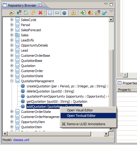
Figure 62: Invoking the Textual Editor from Repository Browser in order to specify a method body
Tip: If you prefer to browse and edit your code in a coarse granularity (or if you are used to programming languages that provide a code for a whole class in a single file), you may choose the following option. Just open the textual editor not for a particular option but for a whole class instead, Figure 63. Similarly, you may open for textual edition even the content of a whole package.
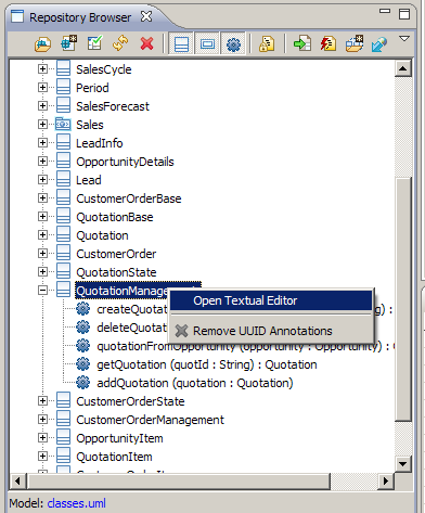
Figure 63: Invoking the Textual Editor for a whole class
When writing the code textually (see Figure 64), you are supported with syntax highlighting (on the other hand, no contextual hint are currently supported).

Figure 64: VIDE textual editor window
A useful validation of the code will occur when storing the method in the repository: invalid names or type errors will be detected when attempting to create model element instances. To store the model in repository use the button “Update UML model with method bodies” – (4) in the Figure 65.)Figure 65: Storing a model in the repository
The language features supported include most of the OCL language and imperative constructs, whose syntax was developed specifically for VIDE. Details are presented in Deliverable D2.1. Here we present only a summary and emphasize some specific features.
As VIDE is intended to deal with persistent data, it may often process data collections. In most cases, those will be Sets or Bags as defined in OCL and appropriate collection-type predefined operations will be available for them. Please note that retrieval of any operation or attribute with multiplicity different than 1..1 produces, according to OCL’s semantics a collection-type result.
We have observed, that the typical business logic in VIDE will usually apply the foreach iterating instruction for updating or transforming results of such types. Note the availability of the auxiliary variable in that iteration, implemented in the syntax uniform with the OCL part:
opportunity.item foreach { i |
q.addQuotationItem(i);
}
When performing object updates please bear in mind the following guidelines:
Any update (like e.g. attribute value assignment or link creation) need to be performed each time on a single object being updated (that matches directly the semantics of respective UML actions). Hence the foreach iteration can be useful to assure that. The only exception from this rule is allowing macroscopic removals of objects with delete statement.
For updating links (that is, instances of UML associations) use respectively the link ... to and unlink ... [ from ... ]. For updating variables or attributes of multiplicity 1..1 use assignment operators ( :=, +=, -=, *=, /=), and for other multiplicities – use insert, replace or delete respectively.
For declaring variables of non-1..1 multiplicities, follow the VIDE syntax for such declarations, which is a hybrid of the syntaxes of OCL and UML that are joined in VIDE:
variabeName: CollectionKind[0..*](TypeName); For example: leadList: Bag[0..*](LeadInfo);
Now, to continue our introductory example, you may specify a method body for the SimpleShop::Order.calculatedTotal method, by opening it for edition in the Textual Editor and providing the following code:
context SimpleShop::Order.calculatedTotal body {
return orderItem->collect(quantity * orderedProduct.price)->sum();
}
As you may see, in this case its body is a pure OCL expression, plus a containing return statement realized by UML’s ReplyAction action.
You may also wish to prepare your model in advance for simpler testing with the model execution feature, by creating an operation in the SimpleShop class, serving for creating sample objects instances for running the model. Let’s name the operation tester() and provide the following sample code for it:
context SimpleShop::SimpleShop.tester body {
prod insert Product create {
productName := 'Premium account';
price := 100;
onSale := true
};
prod insert Product create {
productName := 'Basic account';
price := 30;
onSale := false
};
prod insert Product create {
productName := 'Backup software';
price := 25;
onSale := true
};
prod insert Product create {
productName := 'Password management software';
price := 35;
onSale := true
};
ord insert Order create {
customerName := 'Smith'
};
ord insert Order create {
customerName := 'Brown'
};
ord insert Order create {
customerName := 'XYZ Inc.'
};
ord->select(customerName = 'Smith') with { o |
Item create {
quantity := 1;
link orderedProduct to prod->select(productName = 'Premium account');
link containingOrder to o
};
}
ord->select(customerName = 'Brown') with { o |
Item create {
quantity := 1;
link orderedProduct to prod->select(productName = 'Backup software');
link containingOrder to o
};
Item create {
quantity := 1;
link orderedProduct to prod->select(productName = 'Password management software');
link containingOrder to o
};
}
ord->select(customerName = 'XYZ Inc.') with { o |
Item create {
quantity := 11;
link orderedProduct to prod->select(productName = 'Premium account');
link containingOrder to o
};
Item create {
quantity := 15;
link orderedProduct to prod->select(productName = 'Basic account');
link containingOrder to o
};
}
}
Following the Simple Shop example, we will use the visual editor to implement the behaviour of a method using an activity. To do that, add the operation calculateOrderTotalForCustomer(customer : String) : Integer to the SimpleShop class using the Topcased editor. This method will calculate the sum of all orders that have been placed by a given customer.
After that you can start the visual editor to implement that method by either:
Selecting the new method in the repository browser and right-clicking it as shown in Figure 66. This is the preferred and recommended way as this automatically adds an activity to the model, which implements the selected method if not yet existent.
Starting the UML tree editor and adding an activity for the new method and then right-clicking that activity as shown in Figure 67. Do not forget to add a PackageImport to the UML model for the oclstdlib (in the class where it will be used!), as we will need some types that are defined in it.
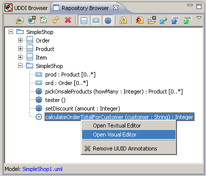
Figure 66: Opening Visual Editor from Repository Browser
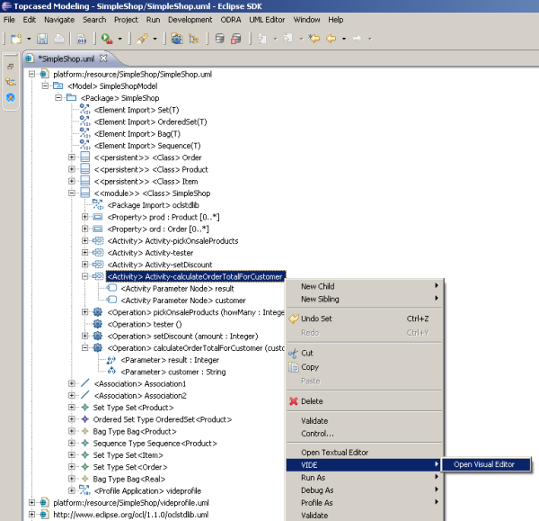
Figure 67: Opening the VIDE visual editor from UML Editor
In the visual editor, use the inner SequenceNode (that represents the body of the method) – create it if not generated automatically – it should be a sibling of the self variable declaration – to include several VIDE constructs selectable from the palette on the right. Just select Variable and click into the editor area to create its declaration as shown in Figure 68. Name it “total” and enter the type Integer into the respective labelled text box. While entering the type name, you can use Ctrl+Space to open the content assist for types. Other text boxes also provide content assists if necessary/possible. Assign the variable the value 0 by adding an AddVariableValueAction from the palette into the SequenceNode. Enter the name of the variable into the according text box of the AddVariableValueAction and enter 0 or another OCL expression into the text box with the value.
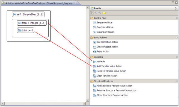
Figure 68: Creating a SequenceNode with a variable that is assigned the value 0
Then, as we want to iterate over all orders of the shop to find orders of the specified customer, we must add an ExpansionRegion into the SequenceNode create an expansion region. The expansion region has two text boxes: one for the iterator (left one) and one for the collection (right one). For the iterator the expansion region suggests by default the name i and you can leave it unchanged. For the collection enter ord, which is a property of a collection type defined in the SimpleShop class.
The creation of the expansion region are shown in Figure 69.

Figure 69: Creating an Expansion Region
As we are interested only in orders from a specific customer, we add a ConditionalNode that will only execute its body if the respective condition holds. Create a new conditional node into the expansion region as illustrated in Figure 70 and enter the condition i.customerName=customer into the respective text box. This condition states that we are only interested in orders by the customer passed as parameter to the method calculateOrderTotalForCustomer.

Figure 70: Creating a Conditional Node in the Visual Editor
As we need the total for the current order, we will call the operation calculatedTotal() on the current order i. For that purpose, we need to create a CallOperationAction as shown in Figure 71. This action has two text boxes. In the upper text box you can enter the name of the target object or class on which the operation will be called. Enter i here. In the lower one enter the name of the operation that should be called (in our example calculatedTotal). If the operation has a return a temporary variable called result is created automatically to hold the return value. Note that if the operation has parameters, the editor will create respective text boxes under the operation name, where you can enter the value for each parameter as an OCL expression.
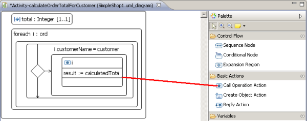
Figure 71: Creating a CallOperationAction in the Visual Editor
Then, we need to add the return value of the operation call to the variable total value using an AddVariableValueAction. To do that, we create an AddVariableValueAction as shown in Figure 72 and enter total on the left side of the assignement and total + result on the right side.
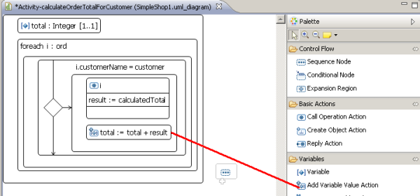
Figure 72: Creating an AddVariableValueAction in the Visual Editor
As a last step, we need to return the calculated total using a ReplyAction, as depicted in Figure 73. Just enter the name of the variable into the respective label of the ReplyAction. The value total is the return of the method calculateOrderTotalForCustomer that we implemented now we the visual editor. When you close the visual editor, your work will be saved automatically.
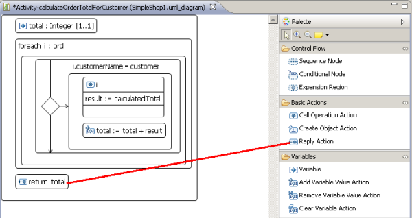
Figure 73: Returning the total value with a ReplyAction
VIDE is provided with Visual Expression Builder (VEB) that allows to replace the textual coding of OCL expressions with their visual, schema-controlled, Query-by-Example style equivalent. The approach was hence called Object Query By Example (OQBE). This functionality is currently fully operational inside Textual Editor. Apart from that – it may be used for specifying expressions embedded into some constructs in Visual Editor, as well as for invoking ad-hoc queries against the Model Execution Engine. In the Textual Editor, the visual expression is represented in the code as a hyperlink, that at the same time plays the role of a subexpression embedded in the code. We may think of such hyperlink subexpression as of an invocation of a virtual view defined inside the environment established by the textual code.
VEB expressions would be especially useful for expressions with complex output structure and / or complex selection criteria, that may be described by example instances and which, on the other hand, would require complicated OCL code to specify them textually.
As will be explained later, the construction of a visual expression implies that the result of such expression would be either Bags or Sequences, whose element type can be either a primitive type, a class or a Tuple of those.
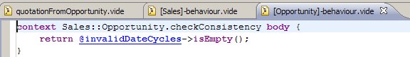
Figure 74: A hyperlink representing visual expression embedded in textual VIDE code
The idea is to hide from the developer the underlying complexity that involves the expression’s diagram location and the actual OCL code automatically generated from it. However, you may spot that details as a greyed-out code section at the end of the textual code.
Should you need to update or review your visual expression, perform Ctrl+click on the hyperlink, which results in opening the VEB diagram for edition (see Figure 75).
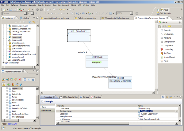
Figure 75: VEB diagram open for edition
The concept of VEB can be summarized with the following informal explanation of the underlying code generation semantics that produces OCL from the diagram.
A single starting point for navigation is identified for a diagram (or – if it consists of more than one independent subgraphs – for each subgraph.
Link navigation connections are traversed and tuples are constructed with a field for each diagram in the navigation.
Then, the selection criteria are applied based on the conditions included in particular examples.
If diagram consists of several independent parts, a Cartesian product of their tuples is constructed.
If there are any sorting criteria, they are then applied according to their priority (relevant if there is more than one criteria).
Finally an output is constructed from the objects or attributes based on the example elements marking with output flags.
For the example shown in Figure 75, the following procedure would be performed by the generated code:
An entry point is identified – this is the self : Opportunity example. Although we do not see the method code for inside which the expression is to be embedded, we may conclude that this must be a method of the Opportunity class.
The self variable expression becomes the start of the code generated.
Then, the two navigation steps, to SalesCycle and then to Period occur, which results with creation of a tuple with three fields of respective three classes in this example (Opportunity, SalesCycle and Period).
Then a selection is performed according to the condition inside the example Period.
Finally a projection is performed to retrieve from this data structure the final result – in this case this will be a Bag of SalesCycle objects.
You may also construct complex result by composing a tuple of two or more named fields. Simply apply more output flags and make sure that in this case each of them is provided with a tuple field name property value.
Cartesian product of independent VEB diagram subexpressions – shall I ever need it?
Usually – not, as this would not be very useful as the final result of an expression. However, we noted so far at least one application. Consider for example, that you are constructing an Order object and need to retrieve one Customer and one Product object to connect the Order to them. Hence you may define a tuple result for those two objects and apply selection criteria (e.g. by identifier attribute comparison). Now, if retrieval is successful you have needed objects readily available in a single-row tuple. Otherwise – you will be alerted by the fact that at least one element is missing – this will result in an empty result of the expression.
VEB diagrams offer a considerably richer validity enforcing compared to the textual code, as well as contextual hints for the names and operations applicable for particular examples and their conditions. Namely, the following hints are available:
When defining an entry point for the diagram (from which the actual generated expression would start), VEB will provide you with a list of program items visible in the context of the expression. Just create the Example model element and consult the Context Name combo list to pick the example’s name and class see Figure 76.
Then, after setting the class of such example, further environment, allowing navigation from it, becomes determined. You need to create a link from existing example by drawing a handle on the diagram and choosing “New element: Example” to create the opposite end of it (see Figure 77).
Now, after selecting the link on the diagram, use the Described by combo list to set appropriate association end to be navigated (see Figure 78). After confirming that selection, the class name of the example on the target end of the link becomes determined form the model and is shown on the diagram.
Finally, you are also assisted when inserting Attribute elements inside example (either for defining output or a condition – here the latter case is illustrated). In case your predicate is constructed as a comparison expression, you have to set the following elements (see Figure 79): (1) Subject (for left-hand of the comparison), (2) Operation (e.g. to select appropriate comparator) and the (3a) Argument (for the right-hand side of the comparison). If performed in the abovementioned sequence, you will be assisted by the contextual hints for Subject, then for Operation. Then you may write the Argument value by hand or – if it is going to be a variable or attribute name rather – the (3b) Context Name field will assist you in selecting the right-hand.
Note, that in case you include syntactically correct variable declarations in your textual code, you will also find them available in the Context Name list.
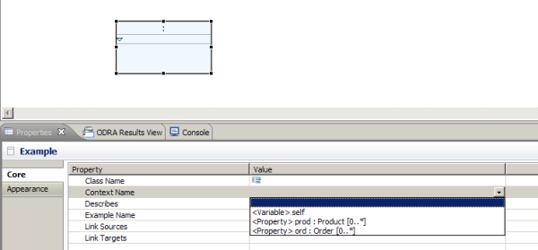
Figure 76: VEB diagram – entry-point example contextual hint
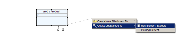
Figure 77: VEB diagram – creating a link navigation
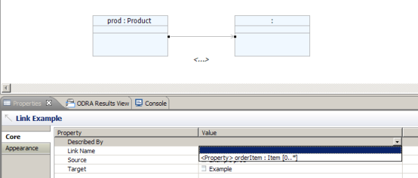
Figure 78: VEB diagram – link navigation contextual hint
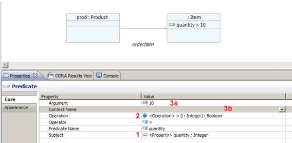
Figure 79: VEB diagram – example attribute, operation and operand selection contextual hint
We may apply the features described above do implement a simple method that uses embedded visual expression. To perform this, open for edition in Textual Editor the operation SimpleShop::SimpleShop.pickOnsaleProducts. Let’s assume that the operation should return a specified number of most expensive products being on sale.
Now, having a cursor in the place of the (currently empty) method definition, write return invoke toolbar command New OQBE. For the diagram file name you may provide e.g. sale ProdsByPrice.oqbe_diagram. In the diagram editor opened, draw the following example (see Figure 80).
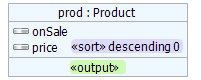
Figure 80: VEB diagram for the do-it-yourself example
To create that diagram, perform the following steps:
Put the Example element onto canvas. In its Context Name property select prod : Product [0..*].
Put Attribute element into the Example. In its Subject property select onSale.
Put Attribute element into the Example. In its Subject property select price.
Put the SortFlag element onto the price element. In its Order property select ascending.
Put the OutputFlag element onto the prod example.
Now, invoke “Generate OCL” command button and accept the default settings. You may close the diagram. Then, put the cursor inside the method body and invoke command button “Insert macro”; select saleProdsByPrice from the popup list.
To complete the method body, append the macro by subSequence operation using the method’s parameter. The resulting code should look as follows.
context SimpleShop::SimpleShop.pickOnsaleProducts body {
return @saleProdsByPrice->subSequence(1, howMany);
}
To ensure the expression is valid, write it into the model by invoking the “Update UML model with method bodies” button in Repository Browser view.
Similar functionality can be used to create expressions inside selected imperative statements of Visual Editor (they include ReplyAction, ExpansionRegion and AddVariableValueAction). For example, you might rewrite the previously discussed sample method calculateOrderTotalForCustomer, to retrieve a collection of relevant subtotals and just returning the sum of them. To achieve this, prepare the following contents of the method and then invoke Visual Expression Builder for specifying the right-hand expression for the totals variable assignment – as shown in Figure 81 and Figure 82.

Figure 81: Visual Editor – method body to be completed by a visual expression
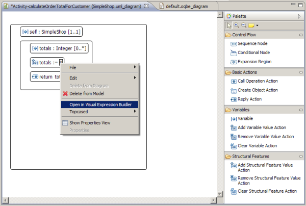
Figure 82: Visual Editor – invocation of Visual Expression Builder from within a method body to create a visual expression
The environment visible to the expression is then automatically determined depending on the expression context inside the Visual Editor and made available to VEB’s contextual hints. The Figure 83 below shows the visual expression for this example.
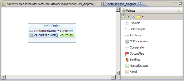
Figure 83: Exemplary visual expression to be used in a method body as a subexpression
Apart from the basic features described above, VEB currently offers several other constructs that extend the amount of OCL expressions that can be represented completely using that editor.
Arbitrary textual OCL embedded. This feature, available through the OclExpression construct allows to write textually an OCL code snippet and made it appear in the generated OCL. The location of that embedding is determined by the example inside which this control was put. The code snippet needs to be formulated so that the names used in it are actually visible within the environment of the class the example represents. See example in Figure 84.
Comparator. This element is introduced to visually present comparisons that span over objects or attributes in separate examples. Its use is illustrated in the sample in Figure 85.
Nested Output. UML object model goes beyond the flat structures know from relational databases and respective QBE solutions. Hence, the OQBE provides a diagrammatic constructs that allows constructing a tuple result whose elements can be collections of simple types or tuples also. Exemplary result structure involving the nested output is illustrated in Figure 86.
For all. This construct provides a region where a fragment of example can be included to define a body of OCL’s forAll operation applied to the example from which a link entering the region is drawn. See example in Figure 87.
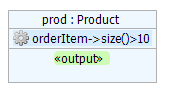
Figure 84: Example illustrating the use of OclExpression element
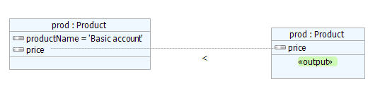
Figure 85: Example illustrating the use of Comparator element

Figure 86: Example illustrating the use of the NestedOutput element in Tuple-typed result

Figure 87: Example illustrating the use of the ForAll element
This feature is based on ODRA system adapted as a Model Execution Engine, which incorporates ODRA code generator, editor interface for passing the code to the engine, and facilities for invoking ad-hoc queries and statements while inside the VIDE editor.
Since not all phases of the work with PIM behaviour specification require it, running the Model Execution Engine was designed to be performed explicitly. This consists of starting the server by starting a respective batch file outside the editor and then invoking the “Connect to existing server” command. To set up the Model Execution Engine, perform the following steps:
Locate the Model Execution Engine runtime (normally, located in ODRA-MEE subdirectory)
Invoke server_recreate.bat batch file, in order to start the engine with no model and with empty database see Figure 88 (alternatively – you may chose the server_run.bat, which will allow to continue with the repository state from previous session.
Successfully run engine should show a command line window as shown in Figure 89. Do not close this window until you finish your work with executing the model.
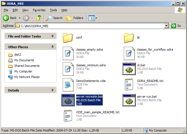
Figure 88: Locating the batch file to start clean instance of Model Execution Engine
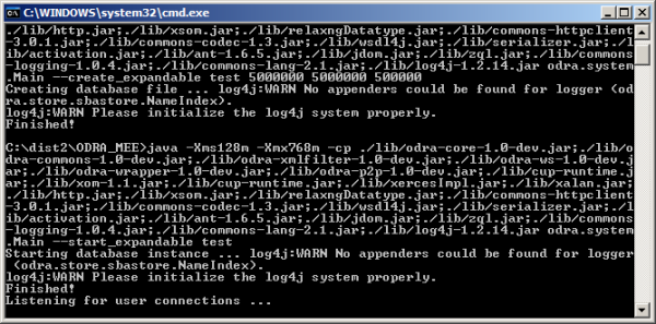
Figure 89: Model Execution Engine while running
Now, from the VIDE perspective, choose the connection command and confirm the default settings in the dialog, as shown in Figure 90.

Figure 90: Connecting from VIDE Editor to Model Execution Engine
The process of providing the model to the Model Execution Engine is rather straightforward, although in the current implementation – not fully transparent. It consists of generating ODRA code from a model and then running it (as a single code installation command) against the server. The steps are as follows:
Make sure to have your model (a .uml file) loaded in the Repository Browser
Choose the code generation command inside the Repository Browser (see Figure 91). You may keep the default settings and go directly to “Finish” command.
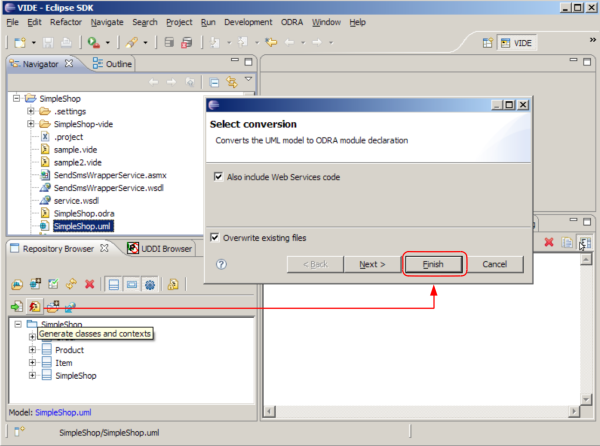
Figure 91: Invoking the code generation for the model being edited
The code generated in shown in an active textual editor window (actually, you don’t have to review this code as it is fully determined by underlying UML model). If the model is complete in terms of the behaviour, you may pass it to the Model Execution Engine: just press the “Execute” button in the main toolbar (see Figure 92).
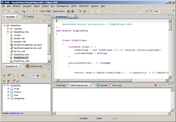
Figure 92: Passing the model code generated to the Model Execution Engine
Note. If you intentionally keep some operations undefined in terms of their behaviour, make sure to put nop; statements in their bodies. Otherwise, the model cannot be run.
Note. Should you need to update your model later and re-send it to the Model Execution Engine, it may be useful to disconnect and reconnect to the engine from the editor.
Now, we are ready to test the behaviour by invoking ad-hoc statements or queries over the model installed in Model Execution Engine. Passing ad-hoc code is performed analogously to providing behaviour to be stored in the model. That is, we are using the textual editor and passing selected code written inside it. However, contrary to regular method bodies, this code is not assigned to particular operation in the model. Hence, you need to specify the class, in the context of which the ad-hoc statements are to be performed. Repository Browser will be used for this purpose. In most cases, you’ll select the «module» stereotyped class as this context. You may think of it as a special, ephemeral method, being added to the class selected, for the time of executing the code.
To proceed with model execution for our sample SimpleShop model, please perform all the steps described earlier in the PIM Executing section. If you ran the code generation over the model and passed its result from the editor to the Model Execution Engine, you should observe the respective message in the “ODRA Results View” window, confirming the successful installation of the model – see Figure 93.
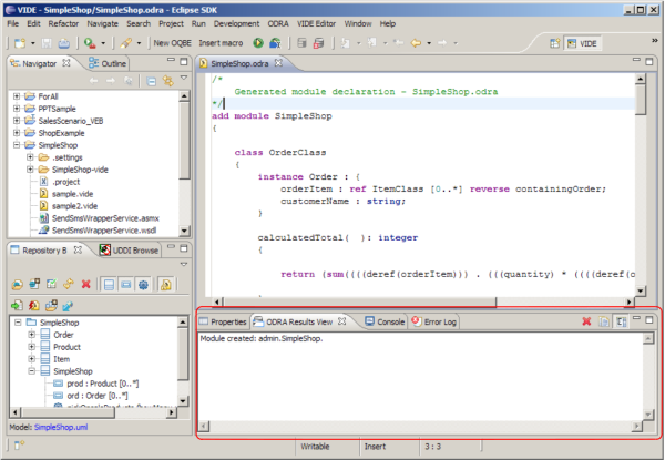
Figure 93: Message confirming the model installation
Now, in the Navigator window, invoke “New > VIDE Textual File” inside your project folder and name the file e.g. sample.vide. Now, you have a textual editor opened for the file and you may start creating code for ad-hoc invocation there.
Let’s run the tester() operation, so we get the sample data created on the server (see Figure 94):
Select the SimpleShop class in the Repository Browser to determine the context of the invocation (step 0)
Highlight the code you are going to invoke in the ad-hoc mode (step 1)
Press the “Execute highlighted code” button (step 2)
Now, you can observe the result of this invocation (in that case it is just an empty collection) in the “ODRA Results View” window.
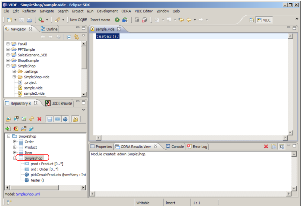
Figure 94: Invoking an ad-hoc statement
Now we can perform other statements as well. For example he results of the prod->select(price>30) query invocation is shown in Figure 95.
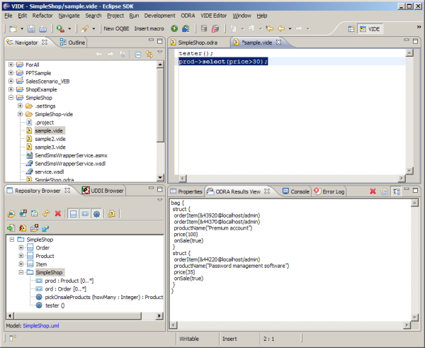
Figure 95: Results of the query invocation inside executable model
Alternatively to running the selected, highlighted code, you may use the “Execute” button, to run all the code in the active document.
You may also use visual expressions in your code to be invoked ad-hoc. Just create a visual expression in a way previously described – that is, using the New OQBE toolbar button, having the context of invocation set in the Repository Browser (see Figure 96). For the purpose of ad-hoc query construction, this will be usually the module-stereotyped class.

Figure 96: Invoking the Visual Expression Builder to create an ad-hoc query OQBE expression
To test the above-mentioned feature in our sample model, perform the following steps:
have open an arbitrary .vide file in the editor to get the New OQBE command available
invoke the Visual Expression Builder using that command button
draw an expression – say – listing the products ordered by Brown (see Figure 97)
generate OCL from it, setting the sample2.vide as the target
insert the resulting macro to the document
run a whole content of the document with “Execute” command button.
The results of the visual query invocation on that sample are shown in Figure 97.
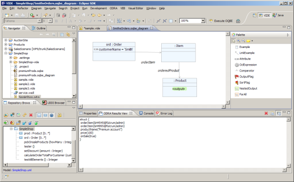
Figure 97: Results of the sample visual query invocation
Since VIDE functionality essentially deals with model levels down to PIM, the step of code generation is very simple:

For Java code generation – invoke a similar command in the Repository Browser called “Generate Java code” or (if this is not yet implemented) – select the .uml file in the Navigator window and choose “VIDE > Generate Code Java” from the contextual menu.
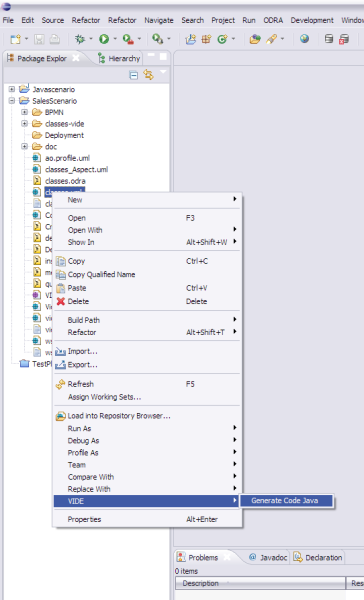
Figure 98: Launching Java Code Generator
Redesign the structure of the sample model, so as to include a separate class Customer. Add a cust attribute in class SimpleShop to keep the instances of this class. Decide, whether you want to keep the ord attribute, or you’d rather only access the Order instances through navigation from cust.
Design an ad-hoc statement – either textually of visually, that lists the names of products with the names of customers who have ordered them