
An initial stage to design is the production of a class model from the business process model developed at CIM level. A behaviour model, typically, an activity chart is produced alongside the class model. The PIM prototyping tool therefore takes as input the business process model file produced by the CIM tool, the VCLL component and applies a set of heuristics to convert elements of the CIM model into class model elements and activity model elements.
The following steps are to be followed in order to develop an initial class and activity model from a business process model (VCLL) file:
Selecting VCLL file
Creating the class and activity diagram files
Displaying the diagrams
To launch the PIM prototyping tool, the user needs to start the Eclipse application first. The PIM prototyping tool is then launched as an Eclipse application using the menu choices Run Run As Eclipse Application. The PIM prototyping tool provides the user with a tree structure to the top left corner (or Package Explorer) from where the VCLL file can be chosen.
The following is the initial PIM prototyping tool’s interface (Figure 49) :
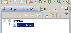
Figure 49: Select the file
The PIM prototyping tool provides the user with two buttons, one for creating an activity diagram, and the other for creating a class diagram. Once the VCLL file has been selected, the user can click any of the buttons “Class diagram” or “Activity diagram” to create either a class diagram or an activity diagram see Figure 50:
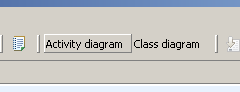
Figure 50: Select the diagram type
When a user clicks, say the “Class diagram” button applies heuristics on the VCLL file to create an XMI file for the class diagram (or for activity diagram if the user had chosen to create an activity diagram). The new XMI file for the class (or/and activity) diagram is displayed on the Package Explorer see Figure 51:

Figure 51: newly created class (details_class.uml) and activity diagram (details_activity.uml) files
To view the class diagram (or activity diagram) the user follows the steps:
right click on the details_class.uml file
choose New on the context menu
Choose Topcased Diagrams
Choose UML Diagram
The user will now be in the screen shown in Figure 52:
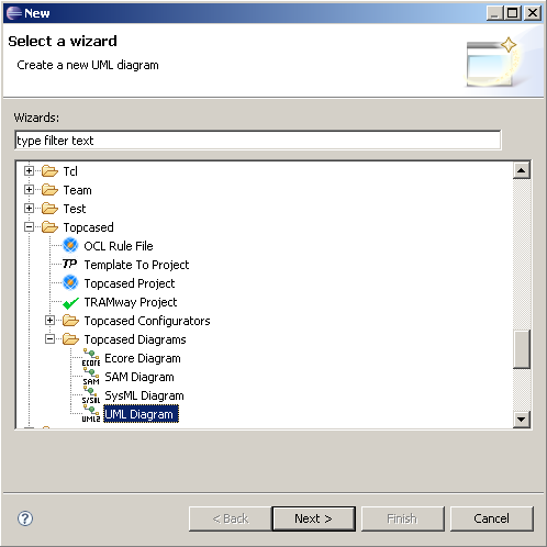
Figure 52: New UML diagram in the Topcased tool
The following further steps are to be followed to create the class diagram:
Select the “package” option
Select the Root diagram to be “Class Diagram”
The user would now be on the screen shown in Figure 53:
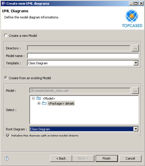
Figure 53: Final step for creating a class diagram
NB: For activity diagrams select the Root diagram to be “Activity Diagram”.
The user should then check “Initialize the model with existing objects” and click on “Finish”.
The following is a class diagram generated and displayed in the Topcased tool following the above steps:

Figure 54: UML class diagram
The objective of this step is to prepare the model for the programmer. This means that the static model should be fully completed ; nothing should be left undefined. To be more concrete, the following elements should be defined :
Attributes type
Associations navigability
Association roles and multiplicities on the navigable sides
Classes, associations, attributes and methods visibilities
Defining association navigabilities lead to two problems :
Determining the navigability of an association
Avoiding bi-directional navigabilities especially between classes not in the same package
Determining the navigability of an association
Usually it one of the most difficult question to answer because it deals with how to make a model ‘runable’. Thanks to VIDE approach that encompasses both structural (static) aspect and behavioural (runable) aspect, it much more easy to find the good navigability with the expected behaviour (activities) in the model.
Avoiding bi-directional navigabilities
Bi-directional associations lead to difficulties on several levels. At the conceptual level, it is always difficult to understand concepts that depends on each other (which is what bi-directional associations say). At the pragmatic (not to say programmatic) level, it introduces interdependencies on software component which is always problematic for integration or unit testing.
The typical answer to remove bi-directional navigability is two split one or both classes in the association and introduce inheritance between split classes as shown Figure 55.
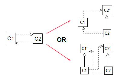
Figure 55: Removing bi-directional navigabilities
In the first modification (upper right model), C2 has been splitted into C2 and C2’ and the association from C1 to C2 moved to C2’, removing the cycle between classes. In the second modification (bottom right model) the same transformation has been applied to C1.