
In the figures below, possible patterns of using VIDE tooling are summarized with activity diagrams. Activities reference sections in this document where respective part of functionality is described. Figure 4 shows the core steps of VIDE-based software development.
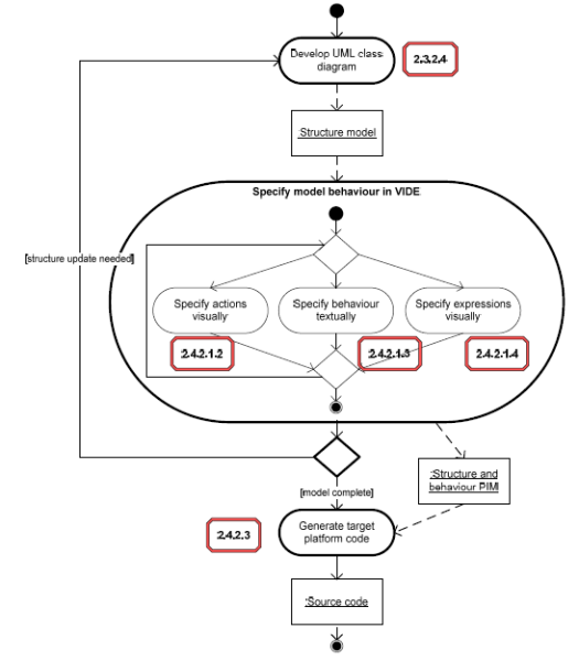
Figure 4: Basic flow of development steps in VIDE
Figure 5 and Figure 6 in turn (single diagram divided into two figures), augments those steps with additional activities (distinguished with blue colour) that may be optionally extend the basic flow of the PIM development (both inside the PIM layer, as well as above it). Those additional activities can be included in different combinations as many of them are mutually independent.
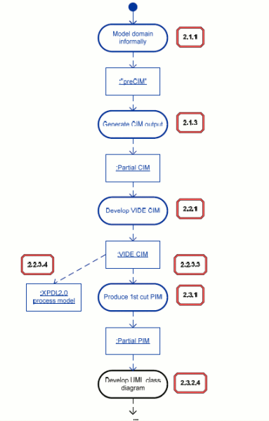
Figure 5: Additional development steps supported by VIDE tool (part 1 of 2)
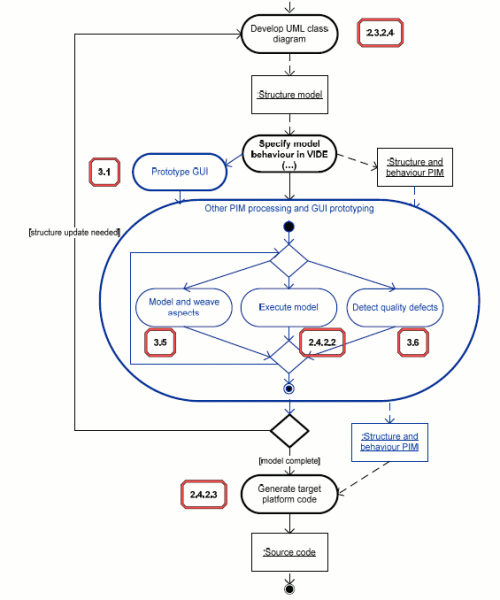
Figure 6: Additional development steps supported by VIDE tool (part 2 of 2)
To sum up, several different usage scenarios can be considered based on the flow described above. Here, we list the workflows available with the tooling made available, as well as few more, possible when combining VIDE with industrial tools involved in the project:
Modelling application structure using UML 2.0 tool and its behaviour details using VIDE textual language. Generation of Java code from the model. This, simplest scenario, involves a UML 2 modelling tool (like Topcased or Softeam Objecteering), plus VIDE Textual PIM Editor – at the PIM layer, and Java Code Generator – at the code generation / model execution layer of the VIDE tool stack.
Extending the scenario (1) or (2) with visualisation of the behaviour model: visual construction of selected actions and activities using visual editor and / or visual and declarative specification of OCL expressions using the UML instance diagram syntax. This scenario involves in addition the modules VIDE Textual PIM Editor and VIDE Visual PIM Editor at the PIM layer.
Using, in the course of any of above scenarios, the capability to execute the platform-independent model in order to ensure they behave as intended. Communication with other software using the Web services connectivity is also available. This scenario involves additionally Model Execution Engine and ODRA Model Compiler modules at the code generation / model execution layer.
Performing, in addition to any of above scenarios a quality defect detection in order to assure the code does not contain constructs that are potentially erroneous or problematic for maintenance. The Quality Defect Detection module of the PIM level is additionally involved here.
Additionally to any of above scenarios – creating and evaluating GUI prototype based on the PIM-level defined application logic. The application behaviour is available through Web service interfaces; if needed, it can be run against the Model Execution Engine. This scenario involves additionally the GUI Prototyping Tool (TNM:WebFace) at the PIM layer.
Supporting any of above scenarios with Aspect Oriented separation of concerns. This scenario uses AO extensions to PIM Editor and PIM repository, plus the Aspect Weaver module, working at PIM layer and isolating the AO specific constructs from other modules consuming the PIM (the code generation / model execution layer in particular).
Performing, in addition to any of above scenarios, the business modelling using VIDE CIM-level language. This scenario additionally involves the CIM Editor and the PIM Prototyping Tool from the CIM layer.
Extending the scenario 7 with additional step for collecting informal requirements and domain knowledge as the entry step to the CIM development. This scenario additionally involves the Domain Analysis Tool from the CIM level.
Extending scenarios 7 or 8 with PIM-level process modelling, that consumes and refines CIM process descriptions to achieve executable processes that can interact with VIDE-defined services or with other software. This scenario involves in addition the Process Designer tool (OfficeObjects®WorkFlow) from the PIM level.
Using VIDE PIM level language for specifying behaviour that integrates existing services (providing VIDE functionality to specialized service development tools). This scenario may involve industrial tools like Altec ONAR (for legacy data integration) or SAP Netweaver (for service engineering).